How to trace roof outlines and specify new buildings
Preconditions:
- Be in Site Definition mode. The Site button in the lower left corner of the workspace will be underlined when in Site Definition mode.

What is a Roof Outline and why is it important?
Roof Outlines encompass the whole building and all the roof faces that make up the building. This also might be called the “gutter line” or “building footprint”. This is used to calculate the Least Horizontal Dimension of the building, which is critical to produce a complete permit package.
Tracing Roof Outlines
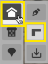
First, select the Roof Outline Tool from the toolbar on the left.
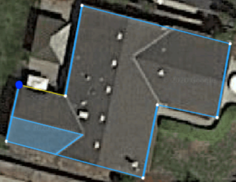
Next, click on the canvas and mark each corner of the roof outline or put another way- trace the entire building. Finish tracing by clicking on the initial point.
Tying the Trace To A Building
After the roof outline is traced, we’ll need to specify what building this outline is associated with. We will either
-
Create a new building
-
Designate that the outline is the same building as a previously specified building
-
Progress automatically past this step because the outline encompasses all other previously drawn roofs. In this case, Lyra can infer that the outline is the same building as the previously drawn roofs.
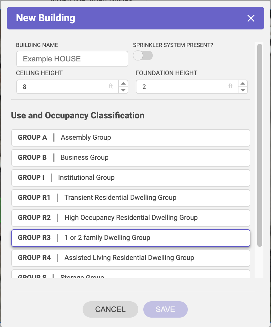
If creating a new building, specify:
-
Presence of a sprinkler system
-
The ceiling height - the ceiling height of any story will do. This, with the foundation height, is used in conjunction with the roof story designation to determine the height of roof tracings.
-
The foundation height - this is used in conjunction with the ceiling height and story specification to determine the height of roof tracings.
-
The use and occupancy classification
Editing Building Names
Building names can be edited from their originally specified name by choosing the Select Tool then look to the properties panel which will now show the previously drawn buildings and roofs. Double click on any name to edit it.

Accounting for imagery skew, and non-orthographic imagery
Occasionally Google Maps aerial imagery isn't perfectly orthographic so there is a skew to it. Below is an example of orthographic imagery and this is how most aerial imagery from Google Maps is. When imagery is more like the second example, perspective, we need to adjust our tracing as if it was orthographic.

Lets use a real world example, below is a home that does not have orthographic imagery (in this case, the building has a small amount of orthographic skew because we can see the eastern side of the building- if it wasn't skewed, we would only see the top-down view). If we were installing solar on the center home then here's how we'd compensate for the non-orthographic imagery.

To help offset the skew, we'll begin tracing the Roof Outline by starting with one of the more 'open' corners of the building. Ideally a corner that shows where the roof begins (in this case, the eastern corners are better suited). If we were to select the western side of the home in this example we cannot tell how much the skew is shifting the roof edge to the west, whereas on the eastern side we can see where the transition from wall to roof occurs.

Continue tracing the Roof Outline to the best of your ability and use Smart Guides to make the process easier. When we get to the side with the most skew (the eastern side in this example) we'll use the Parallel Lines Smart Guide to match tracing from a non-skewed area. You'll notice the the ridge in this photo does not match what we previously traced. This is the correct way to account for the skew.

When the time comes to trace an individual roof face we'll use the Roof Outline trace we just completed as our "anchor." Notice that again in the example below the ridge shown in the imagery varies slightly from our tracing in Lyra. If we were to match the aerial imagery it would be skewed and inaccurate, just as the imagery is but by matching it to the Roof Outline trace we've accounted for and negated the skew.

Next steps
Continue on to trace roof faces, add obstructions, or define other aspects of the site before moving on to System Design such as Adding Site Equipment, Complete Weather Data, and Complete Site Info.